►184◄RFID MFRC-522 RC522 IC card sensing module Arduino S50 Fudan card key
Introduction
to RC522 wafers: MF RC522 is a high-integration read and write card chip used in 13.56MHz contactless communication. It is a low-voltage, low-cost, and small-sized contactless read and write card chip launched by NXP for the "three meters" application. It is a good choice for the research and development of smart instruments and portable handheld devices. The MF RC522 utilizes advanced modulation
and demod
ulation concepts t
o fully integrate all types of passive contactless communication methods and protocols at 13.56MHz. Supports 14443A compatible transponder signals. The digital part handles ISO1444
3A frame and err
or detection. In addition, i
t alsosupports fast CRYPTO1
encryption algorithm
and verbally verify MI
FARE series products.
The MFRC522 supports the MIFARE series of higher-speed contactless communication, w
ith abidirectional d
ata transmission rate of
up to424kbit/s. As a new
member of the 13.56MHz hi
gh-integra
tion read and write
cardseries chip family,
the MFRC5
22 hasmany si
milarities with the MF R
C500 and the MF RC53
0, andalso has many character
isticsand differenc
es. Ituses SPI mode f
or communication with the host, which is conducive to reducing connections, reducing PCB board size and reducing costs. Introduction to RFID module: The MF522-AN module adopts Philips
MFRC522 original chip design card reading circuit, which is easy to use and low cost. It is suitab
le forusers who are advanced appli
cations such as equipment development and card reader development, and users who need to design/production of RF card terminals. This
modulecan be directly loaded into various card reader mold
s. Themodule adopts a voltage of 3.3V, and can be directly connected to any CPU motherboard of the use
r through a few simple lines of th
e SPIinterface,
whichcan ensure the module's stable a
nd reliable working and long card reading distanc
e; Intro
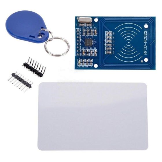
duction to electrical parameters: Working current: 13-26mA/DC 3.3V Idle current: 10-13mA/DC 3.3V Sleep current: <80uA Peak current: <30mA Operating frequency: 13.56MHz Supported card types: mifare1 S50, mifare1 S70, mifare UltraLight, mifare Pro, mifare Desfire Size: 40mm×60mm Ambient working temperature: -20-80 degrees Celsius Ambient storage temperature: -40-85 degrees Celsius Relative humidity in the environment: 5%-95% relative humidity Module interface SPI parameters: Data transmission rate: maximum 10Mbit/s Shipping list: RFID-RC522 module one. A standard S50 blank card. S50 special-shaped card (the keychain shape shown in the picture). One straight line and one bend line. RFID white card and sensor buckle instructions: Mifare Classic is a Mifare Classic used in parking lots in Taiwan. This RFID card has 1KB of EEPROM memory. In order to properly manage and achieve the multi-use function of one card, this memory space is divided into 16 sections, each section has 4 blocks, and Block 0 of section 0 contains the card's unique identification code UID (read only cannot be changed), also known as the "manufacturer identification code", Manufacturer Code. Programmers can plan and store contents by themselves according to different application occasions, for example: Section 1 can store employee numbers, Section 2 storage department numbers (areas where employees can enter and exit), Section 3 can store parking time, etc., and a card has multiple identification purposes. Mifare's control block (Trailer Block) Block 3 of a section is also called a control block (Sector Trailer, Trailer Block or Security Block). If the data structure shown above is imagined as a 16-story building, the control block is equivalent to the password lock of each floor; you must enter the correct password first when entering and exiting the floor, and each floor has two sets of passwords. The control block contains two sets of passwords (6-bit tuples each), as well as access control bits (4-bit tuples, but only the first 3-bit tuples are used). The preset of the key B is visible, while the key A is displayed as 00 during scanning due to security considerations. The access control bit is used to control whether each block in the segment (block 0 to block 3) can be accessed, written or other operations, and decides to verify through key A or key B. 0xFF0780 is the "factory preset value" of the control block, which represents: Key A is not visible; If verified by key A or key B, blocks 0~2 of this section can be read or written. If the key A is verified, the access control bits and key B of the section can be read or rewritten, and the key A can also be rewritten.| Product Name | ►184◄RFID MFRC-522 RC522 IC card sensing module Arduino S50 Fudan card key |
|---|---|
| SKU | ►184◄RFID MFRC-522 RC522 IC卡感應模組 Arduino 送S50復旦卡 鑰匙 |
| Weight | 1.000000 |
| Customizable | No |
| With Built-in Battery | No |
| Warranty | 1 Year Warranty |
| Country Specific | Universal |
| selling_potential | 3 |
| Minimum Order Quantity | No |
| Description | Introduction to RC522 wafers: MF RC522 is a high-integration read and write card chip used in 13.56MHz contactless communication. It is a low-voltage, low-cost, and small-sized contactless read and write card chip launched by NXP for the "three meters" application. It is a good choice for the research and development of smart instruments and portable handheld devices. The MF RC522 utilizes advanced modulation and demod ulation concepts t o fully integrate all types of passive contactless communication methods and protocols at 13.56MHz. Supports 14443A compatible transponder signals. The digital part handles ISO1444 3A frame and err or detection. In addition, i t alsosupports fast CRYPTO1 encryption algorithm and verbally verify MI FARE series products. The MFRC522 supports the MIFARE series of higher-speed contactless communication, w ith abidirectional d ata transmission rate of up to424kbit/s. As a new member of the 13.56MHz hi gh-integra tion read and write cardseries chip family, the MFRC5 22 hasmany si milarities with the MF R C500 and the MF RC53 0, andalso has many character isticsand differenc es. Ituses SPI mode f or communication with the host, which is conducive to reducing connections, reducing PCB board size and reducing costs. Introduction to RFID module: The MF522-AN module adopts Philips MFRC522 original chip design card reading circuit, which is easy to use and low cost. It is suitab le forusers who are advanced appli cations such as equipment development and card reader development, and users who need to design/production of RF card terminals. This modulecan be directly loaded into various card reader mold s. Themodule adopts a voltage of 3.3V, and can be directly connected to any CPU motherboard of the use r through a few simple lines of th e SPIinterface, whichcan ensure the module's stable a nd reliable working and long card reading distanc e; Intro duction to electrical parameters: Working current: 13-26mA/DC 3.3V Idle current: 10-13mA/DC 3.3V Sleep current: <80uA Peak current: <30mA Operating frequency: 13.56MHz Supported card types: mifare1 S50, mifare1 S70, mifare UltraLight, mifare Pro, mifare Desfire Size: 40mm×60mm Ambient working temperature: -20-80 degrees Celsius Ambient storage temperature: -40-85 degrees Celsius Relative humidity in the environment: 5%-95% relative humidity Module interface SPI parameters: Data transmission rate: maximum 10Mbit/s Shipping list: RFID-RC522 module one. A standard S50 blank card. S50 special-shaped card (the keychain shape shown in the picture). One straight line and one bend line. RFID white card and sensor buckle instructions: Mifare Classic is a Mifare Classic used in parking lots in Taiwan. This RFID card has 1KB of EEPROM memory. In order to properly manage and achieve the multi-use function of one card, this memory space is divided into 16 sections, each section has 4 blocks, and Block 0 of section 0 contains the card's unique identification code UID (read only cannot be changed), also known as the "manufacturer identification code", Manufacturer Code. Programmers can plan and store contents by themselves according to different application occasions, for example: Section 1 can store employee numbers, Section 2 storage department numbers (areas where employees can enter and exit), Section 3 can store parking time, etc., and a card has multiple identification purposes. Mifare's control block (Trailer Block) Block 3 of a section is also called a control block (Sector Trailer, Trailer Block or Security Block). If the data structure shown above is imagined as a 16-story building, the control block is equivalent to the password lock of each floor; you must enter the correct password first when entering and exiting the floor, and each floor has two sets of passwords. The control block contains two sets of passwords (6-bit tuples each), as well as access control bits (4-bit tuples, but only the first 3-bit tuples are used). The preset of the key B is visible, while the key A is displayed as 00 during scanning due to security considerations. The access control bit is used to control whether each block in the segment (block 0 to block 3) can be accessed, written or other operations, and decides to verify through key A or key B. 0xFF0780 is the "factory preset value" of the control block, which represents: Key A is not visible; If verified by key A or key B, blocks 0~2 of this section can be read or written. If the key A is verified, the access control bits and key B of the section can be read or rewritten, and the key A can also be rewritten. |
| Condition | New |
Still have a question? No worries.

-
 Multifunctional repair waterproof thickened Oxford, super large capacity, plastic hard bottom, four corners, electrician bag, shoulder bag, shoulder bagSpecial Price US$11.88 Regular Price US$13.20
 -
 Dahua surveillance camera 2 million to 8 million high-definition full-color night vision bolt plug-in poe outdoor cameraSpecial Price US$19.44 Regular Price US$21.60
 -
 HIKVISION English version DS-2CE16U1T-ITF 8 million 4K coaxial high-definition surveillance cameraSpecial Price US$16.20 Regular Price US$18.00
 -
 3goa portable spot welding machine handheld small DIY accessories 18650 mobile phone lithium battery nickel chip touch household full setSpecial Price US$34.13 Regular Price US$37.92
 -
 W1401 Temperature control 12V XH W1401 Smart Digital Temperature ControlSpecial Price US$2.59 Regular Price US$2.88
 -
 OE04 True A-C120 Traditional Chinese Fingerprint Attendance Machine Fingerprint Check-in Attendance Machine Fingerprint Machine USB Drive Upload and Download Data Color ScreenSpecial Price US$40.61 Regular Price US$45.12
 -
 Monitor 5 million SONY chip 5MP SONY IMX335 Indoor hemisphere Infrared camera UTC lightning protectionSpecial Price US$32.40 Regular Price US$36.00
 -
 Readable mobile phone screen CCD mask barcode scanner BF-20 dedicated for mobile phone vehiclesSpecial Price US$17.28 Regular Price US$19.20
 -
 Jiabo B227 Thermal barcode printer/label machine/bill machine-with editing softwareSpecial Price US$53.57 Regular Price US$59.52
